3D PRINTING
3D printing or additive manufacturing is a process of making three
dimensional solid objects from a digital file. The creation of a 3D
printed object is achieved using additive processes. In an additive
process an object is created by laying down successive layers of
material until the entire object is created. Each of these layers can be
seen as a thinly sliced horizontal cross-section of the eventual
object.
How does 3D printing work?
It all starts with making a virtual design of the object you want to
create. This virtual design is made in a CAD (Computer Aided Design)
file using a
3D modeling
program (for the creation of a totally new object) or with the use of a
3D scanner (to copy an existing object). A 3D scanner makes a 3D
digital copy of an object.
3d scanners use different technologies to generate a 3d model such
as time-of-flight, structured / modulated light, volumetric scanning and
many more.
Recently, many IT companies like Microsoft and Google enabled their
hardware to perform 3d scanning, a great example is Microsoft’s Kinect.
This is a clear sign that future hand-held devices like smartphones will
have integrated 3d scanners. Digitizing real objects into 3d models
will become as easy as taking a picture. Prices of 3d scanners range
from very expensive professional industrial devices to 30 USD DIY
devices anyone can make at home.
Processes and technologies
Not all 3D printers use the same technology. There are several ways
to print and all those available are additive, differing mainly in the
way layers are build to create the final object.
Some methods use melting or softening material to produce the layers.
Selective laser sintering (SLS) and fused deposition modeling (FDM) are
the most common technologies using this way of printing. Another method
of printing is when we talk about curing a photo-reactive resin with a
UV laser or another similar power source one layer at a time. The most
common technology using this method is called stereolithography (SLA).
To be more precise: since 2010, the
American Society for Testing and Materials (ASTM) group “
ASTM F42 – Additive Manufacturing”, developed a set of standards that classify the Additive Manufacturing processes into
7 categories according to
Standard Terminology for Additive Manufacturing Technologies. These seven processes are:
- Vat Photopolymerisation
- Material Jetting
- Binder Jetting
- Material Extrusion
- Powder Bed Fusion
- Sheet Lamination
- Directed Energy Deposition
Below you’ll find a short explanation of all of seven processes for 3d printing:
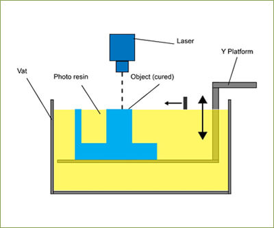
Vat Photopolymerisation
A 3D printer based on the Vat Photopolymerisation method has a
container filled with photopolymer resin which is then hardened with UV
light source.
The most commonly used technology in this processes is
Stereolithography (SLA).
This technology employs a vat of liquid ultraviolet curable
photopolymer resin and an ultraviolet laser to build the object’s layers
one at a time. For each layer, the laser beam traces a cross-section of
the part pattern on the surface of the liquid resin. Exposure to the
ultraviolet laser light cures and solidifies the pattern traced on the
resin and joins it to the layer below.
After the pattern has been traced, the SLA’s elevator platform
descends by a distance equal to the thickness of a single layer,
typically 0.05 mm to 0.15 mm (0.002″ to 0.006″). Then, a resin-filled
blade sweeps across the cross section of the part, re-coating it with
fresh material. On this new liquid surface, the subsequent layer pattern
is traced, joining the previous layer. The complete three dimensional
object is formed by this project. Stereolithography requires the use of
supporting structures which serve to attach the part to the
elevator platform and to hold the object because it floats in the basin
filled with liquid resin. These are removed manually after the object
is finished.
Material Jetting
In this process, material is applied in droplets through a small
diameter nozzle, similar to the way a common inkjet paper printer works,
but it is applied layer-by-layer to a build platform making a 3D object
and then hardened by UV light.
 Binder Jetting
With binder jetting two materials are used: powder base material and a
liquid binder. In the build chamber, powder is spread in equal layers
and binder is applied through jet nozzles that “glue” the powder
particles in the shape of a programmed 3D object. The finished object is
“glued together” by binder remains in the container with the powder
base material. After the print is finished, the remaining powder is
cleaned off and used for 3D printing the next object. This technology
was first developed at the Massachusetts Institute of Technology in 1993
and in 1995 Z Corporation obtained an exclusive license.
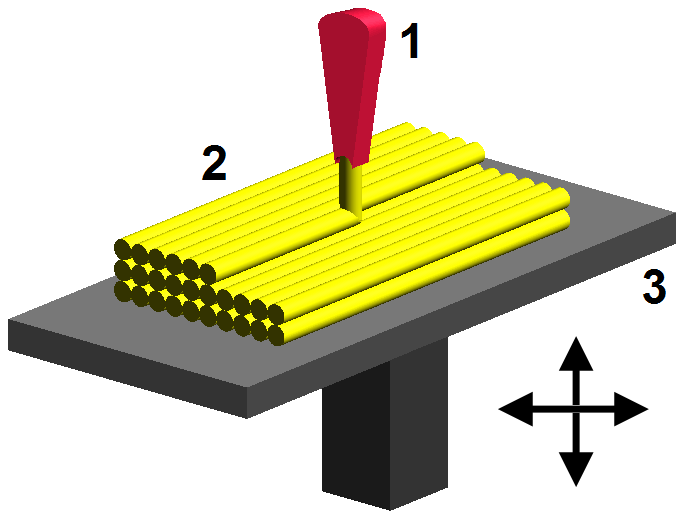
 Material Extrusion
The most commonly used technology in this process is
Fused deposition modeling (FDM)
The FDM technology works using a plastic filament or metal wire which
is unwound from a coil and supplying material to an extrusion nozzle
which can turn the flow on and off. The nozzle is heated to melt the
material and can be moved in both horizontal and vertical directions by a
numerically controlled mechanism, directly controlled by a
computer-aided manufacturing (CAM) software package. The object is
produced by extruding melted material to form layers as the material
hardens immediately after extrusion from the nozzle. This technology is
most widely used with two plastic filament material types:
ABS (Acrylonitrile Butadiene Styrene) and
PLA (Polylactic acid) but many other materials are available ranging in properties from wood filed, conductive, flexible etc.
FDM was invented by Scott Crump in the late 80’s. After patenting this technology he started the company
Stratasys
in 1988. The software that comes with this technology automatically
generates support structures if required. The machine dispenses two
materials, one for the model and one for a disposable support structure
.
Powder Bed Fusion
The most commonly used technology in this processes is
Selective laser sintering (SLS)
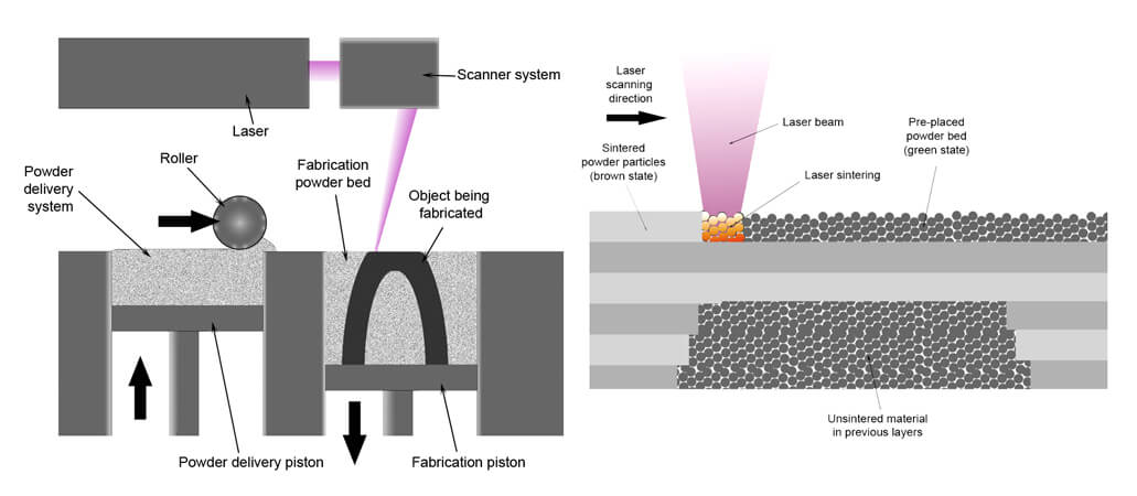
SLS
system schematic. Image source: Wikipedia from user Materialgeeza under
Creative Commons Attribution-Share Alike 3.0 Unported license
This technology uses a high power laser to fuse small particles of
plastic, metal, ceramic or glass powders into a mass that has the
desired three dimensional shape. The laser selectively fuses the
powdered material by scanning the cross-sections (or layers) generated
by the 3D modeling program on the surface of a powder bed. After each
cross-section is scanned, the powder bed is lowered by one layer
thickness. Then a new layer of material is applied on top and the
process is repeated until the object is completed.
All untouched powder remains as it is and becomes a support structure
for the object. Therefore there is no need for any support structure
which is an advantage over SLS and SLA. All unused powder can be used
for the next print. SLS was developed and patented by Dr. Carl Deckard
at the University of Texas in the mid-1980s, under sponsorship of DARPA.
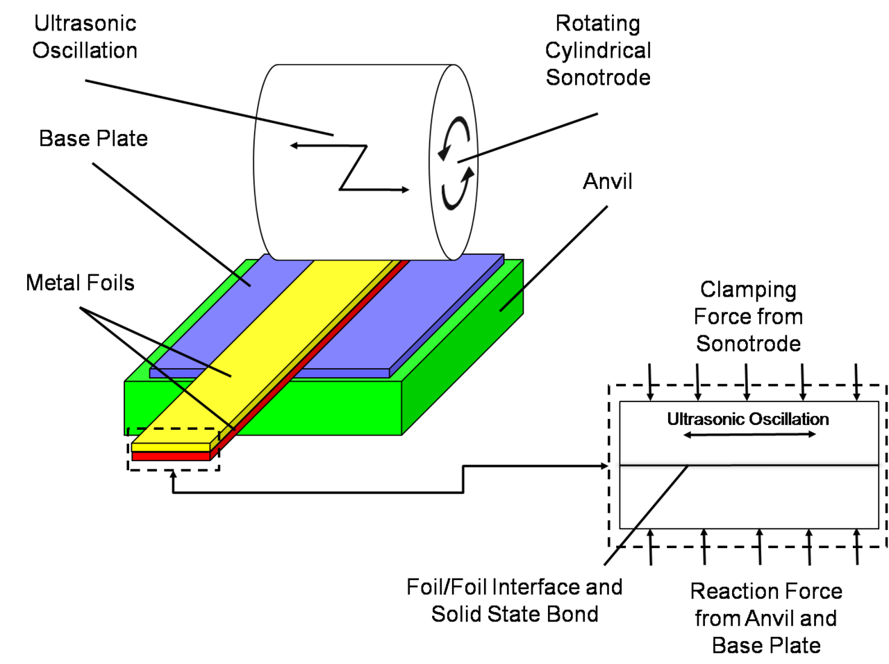
Sheet Lamination
Sheet lamination involves material in sheets which is bound together
with external force. Sheets can be metal, paper or a form of polymer.
Metal sheets are welded together by ultrasonic welding in layers and
then CNC milled into a proper shape. Paper sheets can be used also, but
they are glued by adhesive glue and cut in shape by precise blades.
A leading company in this field is
Mcor Technologies.
Here is a video with a metal sheet 3D printer by Fabrisonic that uses additive manufacturing paired with CNC milling:
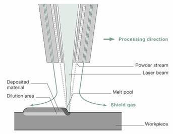
Directed Energy Deposition
This process is mostly used in the high-tech metal industry and in
rapid manufacturing applications. The 3D printing apparatus is usually
attached to a multi-axis robotic arm and consists of a nozzle that
deposits metal powder or wire on a surface and an energy source (laser,
electron beam or plasma arc) that melts it, forming a solid object.